
July 29, 2026
Welded joint categories under ASME VIII (UW-3): where is your weld?

Every time I teach or consult on pressure vessels, the same confusion comes up: someone looks at a drawing, points at a butt weld and says “that one is Category A”. Then points at a fillet and says “that one is Category D”. The logic seems to work, but it is wrong.
Category is not joint type. Category is location.
Paragraph UW-3 of ASME Section VIII Division 1 is short, almost bureaucratic, and it is one of the paragraphs that generates the most rework when read only halfway. It does not say how to weld anything. It answers one question only: where, within the vessel, is that joint? The answer to that question is what later drives the permitted joint type, the degree of examination and the fit-up tolerances.
And there is news: the 2025 edition changed UW-3. As well as revising the first paragraph and two subparagraphs, it brought a fifth category into the figure. Anyone who studied from an older edition learned four categories; today there are five.
Category defines location, not joint type
UW-3 itself opens by stating that the term “category” defines the location of a joint in the vessel, not the type of joint. That sentence is worth rereading.
A butt joint can be Category A, B or C depending on where it is. A corner joint can be Category B, C or D. Joint type (butt, corner, lap, fillet) is the subject of UW-9 and Table UW-12. Category is the subject of the drawing: it is a coordinate, not a geometry.
There is a second detail almost nobody mentions. The category concept exists only because the code needs to direct special requirements at certain joints, and those requirements depend on service, material and thickness. Since they do not apply to every welded joint on the equipment, only the joints that may receive a special requirement are categorised. The text is even more explicit: the special requirements apply to joints of a given category only when specifically so stated.
In other words, categorising a joint does not mean it has an extra requirement. It means that, if some other paragraph directs a requirement by category, that joint will be caught by it.
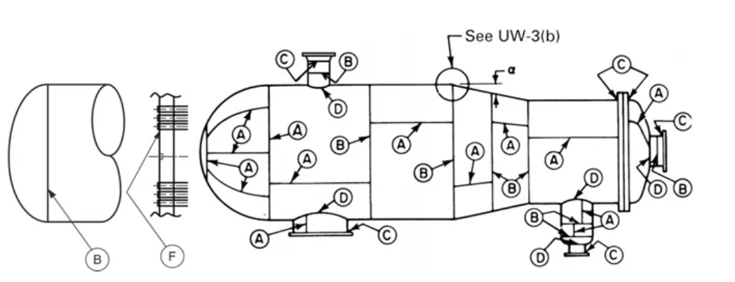
Figure UW-3, ASME BPVC Section VIII Division 1, 2025 edition. Reproduced from the code figure for teaching purposes. Credit: ASME.
What is new in the 2025 edition: Category F
The record of revisions in the 2025 edition marks two changes in UW-3. The first paragraph and subparagraphs (c) and (d) were revised, and Figure UW-3 now includes Category F.
As a result the text now designates joints in Categories A, B, C, D and F, and the new subparagraph (e) gives the definition:
Category F: welded joints attaching tubes to tubesheets in accordance with UW-20.
In practice, the tube-to-tubesheet weld on a heat exchanger is no longer that “outside the classification” case: it now has its own designation within UW-3. Its technical requirements remain in UW-20, which is where the permissible configurations, joint strength rules and qualification live. What has changed is that it now has a name within the category system, which makes it far easier to reference that joint in a welding plan, an ITP and a weld map without inventing terminology.
If your company fabricates heat exchangers and uses an internal procedure with the old four-category list, this is a good moment to update the template.
The five categories in one table
| Category | Location | Typical examples |
|---|---|---|
| A | Longitudinal and spiral joints in the main shell, in communicating chambers, in transitions in diameter or in nozzles. Any joint within a sphere, within a formed or flat head, or within the side plates of a flat-sided vessel. Any butt joint within a flat tubesheet. Circumferential joints connecting hemispherical heads to the shell, to transitions in diameter, to nozzles or to communicating chambers. | Longitudinal shell weld, hemispherical head welded to the shell, seam weld within a head, butt seam within a flat tubesheet |
| B | Circumferential joints in the main shell, in communicating chambers, in nozzles or in transitions in diameter, including the joints between the transition and the cylinder at either the large or the small end. Circumferential joints connecting non-hemispherical heads to the shell, to transitions, to nozzles or to chambers. | Circumferential shell weld, torispherical or ellipsoidal head welded to the shell, cone welded to the cylinder, circumferential seam in a nozzle neck |
| C | Joints connecting flanges, lap joint stub ends, tubesheets or flat heads to the main shell, to formed heads, to transitions in diameter, to nozzles or to communicating chambers. Any joint connecting one side plate to another in a flat-sided vessel. | Flange welded to the nozzle neck, tubesheet welded to the shell, flat head welded to the shell, stub end welded to the pipe |
| D | Joints connecting communicating chambers or nozzles to the main shell, to spheres, to transitions in diameter, to heads, to diffusion-bonded plate packs or to flat-sided vessels, and joints connecting nozzles to communicating chambers. | Nozzle welded to the shell, nozzle welded to the head, communicating chamber welded to the shell |
| F | Welded joints attaching tubes to tubesheets, per UW-20. | Tube-to-tubesheet weld on a heat exchanger |
This is a teaching summary. To classify joints in a contract document, use the official UW-3 text of the edition governing your project.
Two caveats from the text itself are frequently missed. A nozzle at the small end of a transition in diameter is handled by Category B, not D. And within a flat tubesheet, a butt joint is Category A while the attachment of the tubesheet to the shell is Category C: same part, two different categories.
How to decide in practice
When there is doubt on the drawing, the sequence I use is always the same and resolves the great majority of cases.
First: is the joint within a single part (shell, head, cone, nozzle, tubesheet) or connecting two different parts?
If it is within the same part, the next question is orientation. Longitudinal or spiral leads to Category A. Circumferential leads to Category B. A formed head welded from segments, a shell course with a seam weld, a butt seam within a flat tubesheet: all of those are joints within the part.
If it connects two parts, look at what is on each side. Hemispherical head against shell is the exception that moves up to Category A. A non-hemispherical head against the shell is B. A closure element that is neither shell nor formed head (flange, tubesheet, flat head, stub end) is C. A nozzle or communicating chamber penetrating the shell, head or sphere is D. And a tube welded into the tubesheet is F.
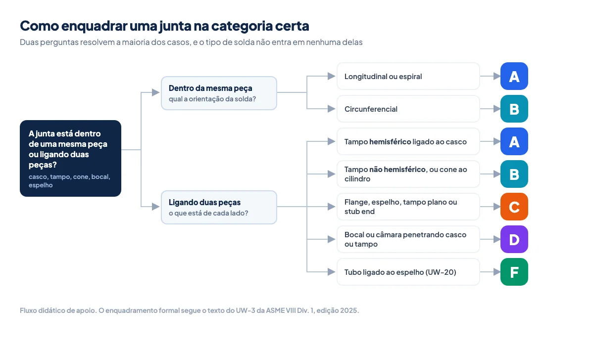
The sequence of questions for classifying the joint. Joint type (butt, corner, fillet) plays no part in this decision.
The angle α: when a circumferential joint stops being a butt joint
This detail in the Category B text decides groove design and turns into an argument in design meetings.
For a transition in diameter, the code establishes that the circumferential joint is considered a butt joint when the half-apex angle α is equal to or less than 30 degrees, and becomes a corner joint when α is greater than 30 degrees. Figure UW-3 itself marks that angle on the cone to the right.
The consequence is direct. Butt joints and corner joints are not the same type in Table UW-12, so they do not carry the same efficiency or the same examination options. A cone with a half-apex angle wider than 30 degrees changes the nature of the joint, even if the fabrication drawing still looks the same as always.
Not every welded joint has a category
This is worth insisting on because it causes doubt in audits. UW-3 itself lists joints that do not receive a category designation, and the list is not exhaustive. It includes the corner joints of sketches (a), (c) and (d) of Figure UEJ-3-1 in Part UEJ, the jacket closure welds of Table 4.11.1 of Division 2, the diffusion bonds in diffusion-bonded plate packs, and the fillet welds of Figure UEB-13 in Part UEB.
For those uncategorised joints, the code clarifies that, unless limited elsewhere in the Division, the joint types permitted by UW-9(a) apply.
Beyond those, welds on non-pressure parts such as saddles, supports and clips naturally fall outside the category classification and are handled in other paragraphs.
Why category changes your design and your inspection
This is where UW-3 stops being bureaucracy. Category is the key other paragraphs use to demand different things of different joints. The four places it appears most:
Permitted joint type and efficiency (UW-9 and Table UW-12). Table UW-12 lists joint types with their efficiencies and limitations, and indicates for which categories each type may be used. Not every type is accepted in every category. A type that suits a Category B circumferential joint may not be accepted in a Category A longitudinal joint, precisely because the membrane stress in the circumferential direction is twice the longitudinal in a cylinder.
Degree of radiographic examination (UW-11). The requirements for full or spot radiography, or for exemption, are written around category and joint type. That is why the inspection plan starts with joint categorisation: without it, you cannot build the NDT map for the equipment.
Special services (UW-2). Lethal service, low temperature and unfired steam boilers impose restrictions that the code addresses by category.
Maximum misalignment (Table UW-33). The offset tolerance at fit-up is given in two columns: longitudinal joints (Category A) and circumferential joints (Categories B, C and D). For the same thickness, the longitudinal joint permits less misalignment. I have seen joints rejected at dimensional inspection because the fitter applied the circumferential tolerance to a longitudinal weld.
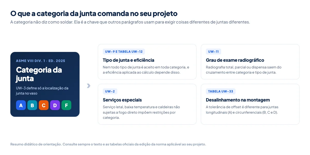
Category is the entry key to the requirements for joint type, examination and fit-up. Teaching summary - always check the current code text.
Where categorisation usually goes wrong
Errors that appear frequently in drawings and welding plans:
Treating a hemispherical head like any other head. The circumferential joint connecting head to shell is Category B when the head is ellipsoidal or torispherical, but rises to Category A when the head is hemispherical. That changes the permitted joint type and changes the examination. It is the most expensive mistake on this list, because it only surfaces at NDT.
Calling every nozzle weld Category D. The nozzle-to-shell connection is D. But the longitudinal weld in the nozzle neck is A, the circumferential seam in the neck is B, and the flange welded at the end is C. A single nozzle can carry three different categories besides D.
Using the old four-category list. After the 2025 edition, an internal procedure recognising only A, B, C and D is out of date. Heat exchangers have Category F.
Categorising by the type of weld on the drawing. Back to the start of the article: if the criterion used was “it is a butt weld, so it is A”, the categorisation is wrong by construction, even when it gets the right answer by coincidence.
Joint categorisation is not a standalone exercise. It is the basis of the welding plan and the weld map, which in turn feed the ITP and the inspection plan. Before that point, each joint still needs a compatible qualified WPS, and that is where ASME IX comes in. One feeds the other: Section VIII says what the joint has to be, and Section IX says how to prove you can weld it.
If joint and weld terminology still causes doubt on your team, it is worth going through the welding terminology glossary first.
Frequently asked questions
Is joint category the same thing as joint type? No. Category says where the joint is in the vessel; type says how it is made (full penetration butt, corner, lap, fillet). The two intersect in Table UW-12, but they are independent concepts.
How many categories are there today? Five: A, B, C, D and F, per UW-3 of the 2025 edition. There is no Category E in this system.
Does the tube-to-tubesheet weld have a category? It does now. In the 2025 edition it is Category F, and its technical requirements remain in UW-20. In earlier editions that joint had no category designation.
Does ASME VIII Division 2 use the same categories? Division 2 also works with joint categories and the concept is equivalent, but the requirements associated with each are specific to Division 2. Do not copy the classification from one division to the other without checking.
Does every welded joint on a vessel have a category? No. UW-3 itself lists joints that fall outside, such as certain corner joints in Part UEJ and the fillet welds in Part UEB, plus welds on non-pressure parts. For uncategorised joints, the types permitted by UW-9(a) apply, unless limited elsewhere in the code.
To close
UW-3 is a one-page paragraph that decides the NDT cost of an entire vessel. Categorising wrongly means radiographing a joint that did not need it, or worse, failing to radiograph a joint that did and finding out in the client’s audit.
If your shop is putting together the weld map for a piece of equipment and wants confidence in the classification, the joint type definition and the examination plan, XP does that work alongside your engineering team: ITP and welding plan, coordination of non-destructive testing and qualification of the WPSs each of those joints will demand.
If your team’s next step is welding documentation, start with the ASME WPS template in Excel, which is free, or with the course Writing a WPS - ASME IX.