
Padeye Weld Size Calculator
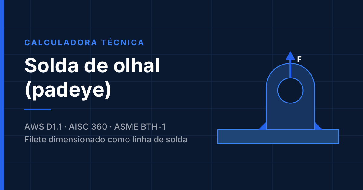
Continuous fillet weld at the padeye base, sized by the weld-line method (the weld group treated as a line).
Results
Why the "quick" padeye weld calculation misleads you
A simplified example circulates widely online: a 50 kN force, a padeye 80 mm at the base and 20 mm thick, a continuous fillet weld around the 200 mm perimeter, an allowable stress of 120 MPa. Dividing force by stress gives an area of 416.7 mm², a throat of 2.08 mm and the conclusion "adopt a fillet with a 4 mm throat". The arithmetic is right - the model is what is incomplete.
That calculation assumes the load is purely vertical, centred and static, and that the whole weld works equally in shear. A real padeye is almost never like that. It has height, so the load creates a moment at the base; the sling is rarely perfectly aligned, so anout-of-plane component appears; and lifting has a dynamic effect.
Run the calculator above with the same 50 kN and a dynamic factor of 1.0, but with just 5° out of plane and the load applied 100 mm above the base: the required throat goes from 2.08 mm to about 4.17 mm - double, from an assembly imperfection nobody would consider abnormal. That is why a padeye is calculated as a weld group under combined loading, not as a simple area.
The method used in this calculator
The weld group is treated as a line (the method established by Blodgett and adopted in structural design practice): the length and section moduli of the welded perimeter are calculated with a unit throat, the resultant force is obtained in N/mm, and only at the end is it converted into a throat and a leg. The steps are:
- Design load: Fd = F × dynamic factor.
- Resolution: Fz = Fd·cosβ·cosα (tension normal to the base), Fx = Fd·cosβ·sinα (in plane), Fy = Fd·sinβ (out of plane).
- Properties of the welded perimeter (weld all around): Lw = 2(L + t), Sx = L·t + t²/3, Sy = t·L + L²/3.
- Moments at the base: Mx = Fy·h and My = Fx·h.
- Force per millimetre of weld: fz = Fz/Lw + Mx/Sx + My/Sy, fx = Fx/Lw, fy = Fy/Lw.
- Resultant: fr = √(fz² + fx² + fy²).
- Required throat: a = fr / τall; leg of an equal-leg fillet: z = a·√2 ≈ 1.41·a.
Note the critical point: the modulus Sx, which resists the out-of-plane moment, depends on the thickness of the padeye. A 20 mm padeye has a lever arm of only 10 mm for that moment. It is the weakest direction of the joint and the one that most often fails the check - and the one the simplified calculation ignores entirely.
Allowable stress: what the code requires
The nominal shear strength on the effective throat of a fillet weld is 0.60·FEXX(AISC 360, Section J2.4, where FEXX is the filler metal strength). What differs between criteria is the safety factor applied:
- AISC 360 – ASD: Ω = 2.00 → τall = 0.30·FEXX (145.5 MPa for E70XX electrode).
- ASME BTH-1 (below-the-hook lifting devices) – Design Category A: Nd = 2.00, used where loads and conditions of use are well defined.
- ASME BTH-1 – Design Category B: Nd = 3.00, for severe or indeterminate service conditions - which covers most field lifts.
Category B is not over-refinement: it is the code's recognition that the real lifting load is uncertain. Add to that the BTH-1 Service Class (0 to 4), which sets the fatigue check as a function of the number of cycles - a padeye on a device used daily is not sized like a padeye for a single erection lift.
The calculator applies the code conservatively in two respects: it does not use the AISC directional strength increase (1.0 + 0.50·sin1.5θ), permitted when the load is not parallel to the weld axis, and it sums all components vectorially at the most highly loaded point.
Minimum and maximum leg size: the code decides before the calculation does
Two checks independent of the load, which fail a lot of "calculated" fillets:
- Minimum leg size (AWS D1.1, minimum fillet weld size table, as a function of the thickness of the thicker part of the joint): 3 mm up to 6 mm thickness; 5 mm over 6 up to 12 mm; 6 mm over 12 up to 20 mm; 8 mm over 20 mm. It exists to ensure sufficient heat input and to avoid rapid cooling and cracking - it has nothing to do with the load.
- Maximum leg size along a free edge (AISC 360, J2.2b): equal to the plate thickness if less than 6 mm; thickness minus 2 mm otherwise.
In the original example, with a 25 mm base plate, the code minimum leg is 8 mm - twice the "adopt 4 mm" of the simplified calculation. The load did not govern; the code did.
Do not forget the base metal
No weld is stronger than the material it anchors into. The calculator checks shear in the padeye (0.60·Fu/Ω = 0.30·Fu, AISC 360 J4.2). Beyond that, padeye design still has to cover: bearing and tear-out at the pin hole, net section area, pin sizing, bending of the base plate, the need for cheek plates, and - when the base plate is loaded through its thickness - the risk oflamellar tearing, which calls for material with through-thickness ductility (ASTM A770 / Z35) and, in many cases, ultrasonic testing of the plate before welding.
Critical equipment and oil & gas: a fillet will not do
Everything above applies to sizing a fillet weld. But there is a class of application where a fillet is simply not an acceptable solution - and that is the part the simplified example never tells you.
On critical equipment, on live-load lifting padeyes and above all inoil and gas (onshore and offshore), the typical contractual and code requirement is that the padeye weld be complete joint penetration (CJP), with a prepared groove, qualified welding and full volumetric inspection. The reasons are technical, not bureaucratic:
- A fillet cannot be volumetrically inspected. The geometry of a fillet prevents reliable ultrasonic scanning of the root and makes radiography uninterpretable. There is no way to demonstrate the absence of lack of fusion at the root - exactly where cracks start. With complete penetration, UT and RT become applicable.
- The fillet root is a built-in notch. Under cyclic loading and under lifting loads (with a dynamic component and reversal), the unfused root acts as a pre-existing crack, dropping the fatigue category of the joint.
- Consequence of failure. A padeye that lets go means a load in free fall onto people and onto pressurised equipment. The design criterion stops being economic and becomes one of process safety.
The non-destructive testing package usually required in these cases:
- Surface testing - PT (dye penetrant) or MT (magnetic particle): 100% of the welds, including the weld toes and the areas where temporary attachments were removed. On ferromagnetic materials MT is the preferred method, since it also detects slightly subsurface discontinuities. On austenitic and non-ferrous materials, PT.
- Volumetric testing - UT (conventional, phased array or TOFD) or RT (radiography):100% of the complete penetration weld, to detect lack of fusion, lack of penetration, cracks and internal inclusions.
- Testing after heat treatment and after a delay period where the material is susceptible to hydrogen induced cold cracking - typically 24 to 48 hours after welding on higher-strength and thicker steels.
- NDT after removal: when the temporary padeye is cut off, the area has to be ground back to the base metal and re-inspected by PT or MT - cutting flush and "leaving the mark" is a classic source of cracking in the shell of the equipment.
Add to that the requirements accompanying the package: a WPS qualified for the actual joint and thickness, welders qualified in the position of execution, control of preheat and interpass temperature, low-hydrogen consumables with baking control, heat treatment where applicable and, in sour service, the hardness limits of NACE MR0175 / ISO 15156. When the padeye is welded to the shell of a vessel or to piping, the weld becomes part of the scope of the equipment's design code (ASME VIII, ASME B31.3) and also falls under client specifications, such as the Petrobras welding standards.
Checklist before releasing the drawing
- Does the design load include a dynamic factor and the device safety factor?
- Has an out-of-plane component been considered (a usual minimum of 5%, or the actual sling angle)?
- Has the moment from the height of the hole been checked in the weld group?
- Does the leg meet the code minimum for the thickness of the thicker part?
- Does the leg respect the maximum at a free edge?
- Has the base metal been checked (shear, net section, bearing at the hole, lamellar tearing)?
- Is the application critical or oil and gas? If so: complete penetration, with PT/MT and UT/RT defined on the drawing and in the inspection plan.
- Is there a WPS/PQR covering the joint, the thickness and the position? Is the acceptance criterion stated?
This calculator is a quick verification and teaching tool. The final calculation is the responsibility of the designer, based on the current edition of the applicable code and the contractual requirements of the project.