July 15, 2024
Welding terminology: a complete glossary of technical terms
Terminology
To be precise when discussing anything to do with welding, we need to know the technical terms of the process, so we can all speak one standardised language everyone understands.
This post covers the technical terms only; each subject will be explored in depth in future articles.
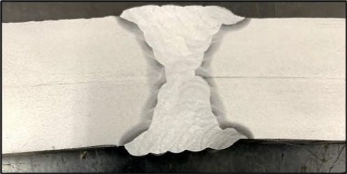
WELD
The weld is the result of the welding process, that is, the fused metal in a welded joint.
WELDING
The technique used to join two or more parts of a structure or component while ensuring continuity of the material.
The parts involved in welding
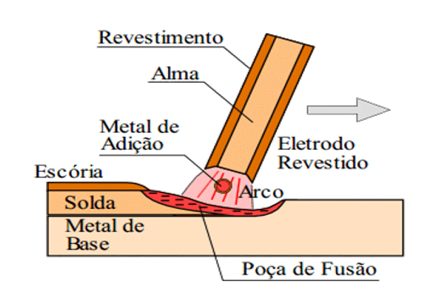
- Base metal - the metal to be welded. It may be plate, pipe, beam, angle, bar and so on.
- Filler metal - used to join the parts being welded. Covered electrode, filler rod, solid wire (bare electrode) and flux-cored wire (tubular electrode).
- Weld pool - material fused (changed from the solid to the liquid state) during fusion welding, made up of base metal plus filler metal where applicable.
- Weld metal, or weld - the result of the welding process.
- Electrode core - the metallic core of a covered electrode.
- Electrode covering - the powdered material surrounding the electrode, whose function is to stabilise the arc, protect the weld pool, form slag and supply alloying elements.
Details of a joint to be welded
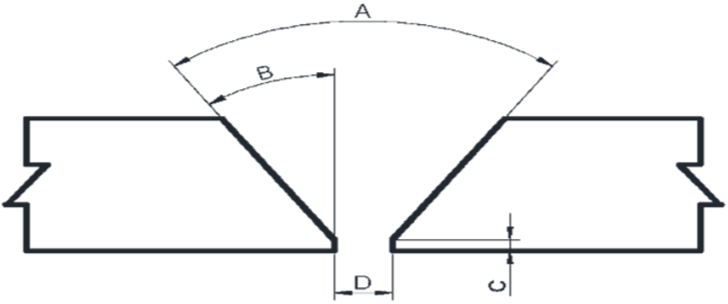
- A: Groove angle: the total included angle between the prepared edges of the components.
- B: Bevel angle: the angle formed between the prepared edge of the component and a plane perpendicular to the component surface (considering one side of the joint only).
- C: Root face (land): the portion of the groove face adjacent to the joint root.
- D: Root opening: the minimum distance separating the components to be joined by welding or allied processes.
- E: Thickness: the base metal dimension to be welded.
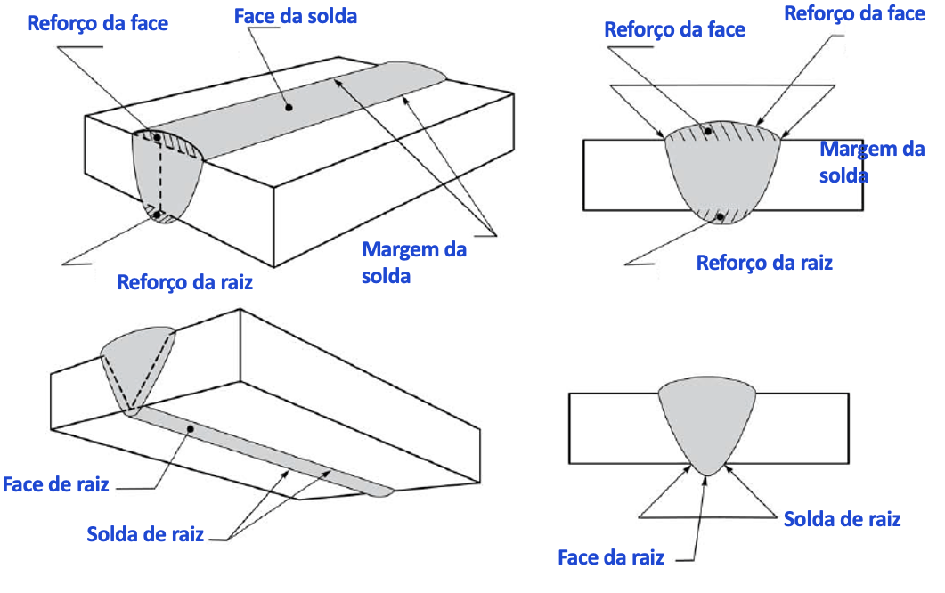
- Joint root: the portion of the joint to be welded where the members are closest to one another (region D in the figure).
- Weld root: the points at which the back of the weld intersects the base metal surfaces (the region seen from below at point D in the figure).
- Weld face: the surface opposite the root.
- Weld toe: the line where the weld face meets the base metal surface.
Pass structure
- Pass: the deposit of material obtained by the progression of a single weld pool (weld bead).
- Layer: the deposit of one or more passes at the same level.
- Root pass: the pass that joins the two root faces.
- Hot pass: the pass made immediately after the root pass to reinforce it.
- Fill pass: the pass whose function is to build volume in the joint.
- Cap pass: the pass on the face of the joint, which is visible after welding.
Example:
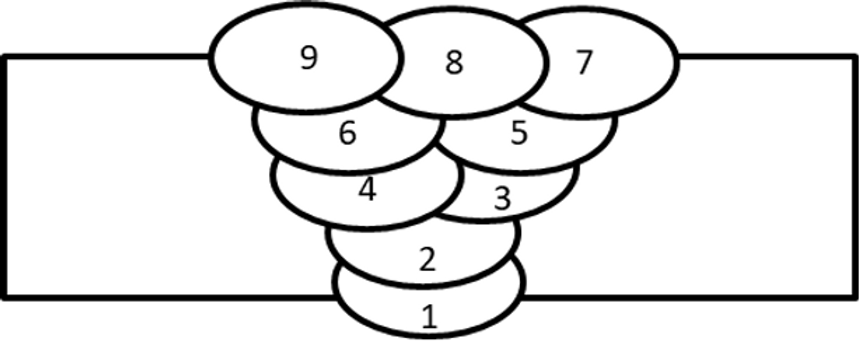
- Pass 1 - layer 1 - root pass.
- Pass 2 - layer 2 - root reinforcement pass, or hot pass.
- Passes 3 and 4 - layer 3 - fill passes.
- Passes 5 and 6 - layer 4 - fill passes.
- Passes 7, 8 and 9 - layer 5 - cap passes.
Zones of a welded joint
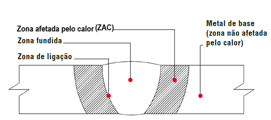
- Heat Affected Zone (HAZ): the region of the base metal that was heated above a certain temperature and underwent changes in microstructure and/or in mechanical or chemical properties.
- Fusion zone: the region melted during welding (weld metal).
- Bond zone: the transition region between the fusion zone and the base metal that stayed solid. Also known as the fusion line.
- Unaffected zone: base metal with no changes.
Electrical properties in welding
- Welding current (A): the electrical current flowing through the electrode while making a weld. Unit: amperes (A).
- Voltage (V): the electrical potential maintaining the arc. Unit: volts (V).
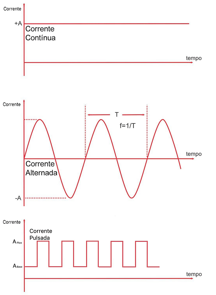
- Direct current: current with fixed polarity.
- Alternating current: current whose polarity alternates over time.
- Pulsed current: current that varies according to the transfer needs of the arc, producing a square or sinusoidal waveform.
- Background current: the current needed to maintain the arc and form the metal droplet. Applicable to pulsed current only.
- Peak current: the current peak needed for the metal droplet to transfer into the weld pool. Applicable to pulsed current only.
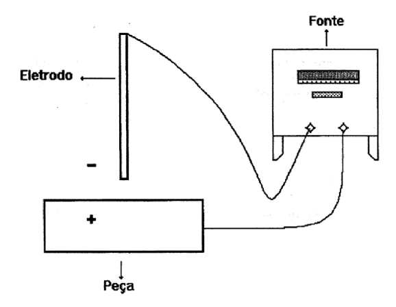
Straight polarity (DCEN): the connection for direct current welding in which electrons travel from the electrode to the workpiece. The workpiece is connected to the positive pole and the electrode to the negative pole. The positive pole is always hotter than the negative, because it receives the electrons. DCEN - GTAW / SMAW processes.
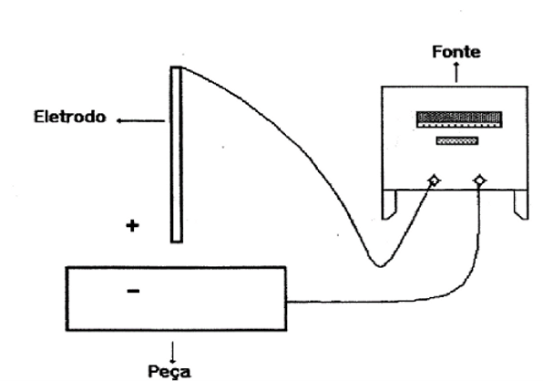
Reverse polarity (DCEP): the connection for direct current welding in which electrons travel from the workpiece to the electrode. The workpiece is connected to the negative pole and the electrode to the positive pole, concentrating heat at the electrode. Usual for processes with continuous or semi-automatic consumable feed. DCEP - FCAW / GMAW / SAW / SMAW (overlay welding).
Welding technique
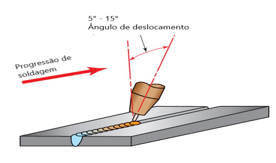
- Travel angle: the angle formed between the axis of the electrode and a reference line perpendicular to the weld axis, in a plane determined by the electrode axis and the weld axis.
- Work angle: the angle an electrode makes with a reference line perpendicular to the plate surface, passing through the centre of the groove, in a plane perpendicular to the weld axis.
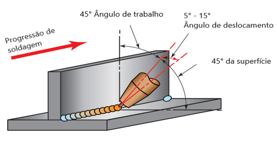
Welding progression
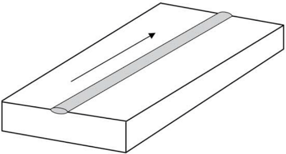
Stringer: when the pass is made without weaving the electrode.
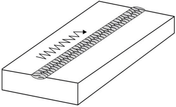
Weave: when the pass is made with the electrode weaving.
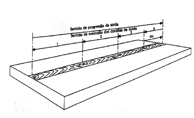
Back-step technique: depending on plate thickness and weld length, the plate tends to distort along the length of the weld, so the back-step technique is recommended: the welder divides the total length into several welding stages, welding against the general direction of progression of the weld, as shown below: