
July 24, 2024
Welding defects: main types, causes and how to avoid them

Introduction
Welding defects are unacceptable imperfections that occur during welding and can significantly compromise the mechanical strength, durability and functionality of a welded joint, potentially causing catastrophic results while the welded equipment is in service. In this article we look at the main types of welding defect, their causes, their consequences and the methods for preventing and correcting them.
Indication, discontinuity and defect
During joint inspection we come across three terms that appear to mean the same thing but differ:
- Indication: the term used to classify an imperfection found during inspection that has not yet been assessed as accepted or rejected against the acceptance criteria.
- Discontinuity: an imperfection, previously classified as an indication, whose characteristics, quantity and dimensions are accepted by the acceptance criteria, so no repair is required. The term discontinuity reflects the fact that it is an interruption in the typical structure of a welded joint - the homogeneity of physical, mechanical or metallurgical characteristics.
- Defect: an imperfection, previously classified as an indication, whose characteristics, quantity and dimensions are rejected by the acceptance criteria, so the joint has to be repaired.
Which welding discontinuity is accepted and which is rejected?
There is an enormous variety of end products containing welded parts, from the simple - a cooker, a chair, a table - through to highly complex, technological and critical equipment such as a rocket, a nuclear power plant or subsea oil and gas pipeline. Given that, a discontinuity can be extremely critical in one application, and therefore a defect, while being irrelevant in another product where it is comfortably accepted. For that reason each type and application of welded equipment has specific codes setting acceptance criteria for the product, such as DNV-ST-F101, ISO 5817, AWS D1.1, AWS D1.6, ASME VIII Div. 1 or 2, and many others.
Location of welding defects
There are two types of welding defect based on location:
Surface defects
- Surface welding defects are those appearing on the surface of the weld, visible to the naked eye or by non-destructive testing (NDT) methods that detect only surface-breaking discontinuities, such as dye penetrant (PT) or magnetic particle (MT). Examples of surface defects: porosity, undercut, overlap, surface cracks, underfill, spatter, excessive penetration and arc strikes.
Volumetric defects
- Volumetric welding defects are those located inside the weld, not open to the surface of the material, and not visible to the naked eye or by surface testing. They can only be detected by volumetric NDT such as radiography (RT) and ultrasonics (UT). Examples of volumetric defects: lack of fusion, lack of penetration, slag inclusion, internal porosity and internal cracks.
Types of welding defect
Porosity
Porosity is a cavity formed by gas trapped inside the weld bead: during fusion the metal solidified before all the gases produced by the process had escaped. Porosity may be spherical or elongated (wormhole).
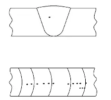
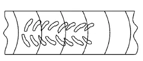
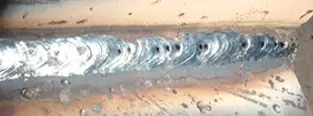
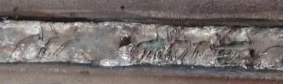
How do you avoid porosity?
- Remove contamination from the joint: mill scale, plasma and oxy-fuel cutting dross, oil, grease and moisture.
- Check that shielding gas flow is correct for the process and the electrical characteristics (check the WPS). Too little or too much gas both cause porosity.
- Check that consumables were correctly baked (covered electrodes and submerged arc flux) and that they have not been exposed to moisture (all consumables).
- Inadequate electrical parameters and an excessively long arc can cause porosity.
- Check for draughts near the welding bench and shield it with screens or welding curtains. Wind removes and/or contaminates the shielding gas during welding, causing porosity.
- Clean the nozzle to clear the shielding gas path (MIG/MAG and flux-cored).
Lack of fusion
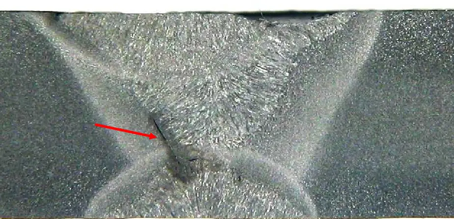
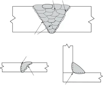
Lack of fusion occurs when the weld metal does not properly fuse to the base metal or between weld passes, because of insufficient heating of the base metal (or adjacent pass) resulting from incorrect manipulation of the weld pool.
How do you avoid lack of fusion?
- Set the electrical parameters correctly. Parameters that are too low can cause lack of fusion.
- Manipulate the weld pool so as to fuse every element of the joint properly (base metal 1, base metal 2 and the adjacent bead).
- Clean the weld surface before welding.
Undercut
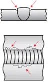
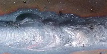
Undercut is a defect characterised by a sharp groove at the weld toe, between the bead and the base metal, formed when the base metal melted and was drawn into the weld metal. These grooves reduce material thickness and act as stress raisers.
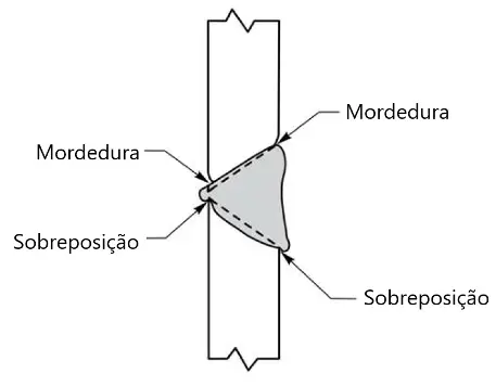
How do you avoid undercut?
- Reduce the electrical parameters and the arc length.
- Reduce travel speed.
- Manipulate the torch correctly so that material is fused and deposited properly onto the base metal.
Weld spatter
Spatter consists of droplets of molten material expelled from the weld pool and thrown in random directions, which may fuse onto the surface of the weld or of the base metal near the pool.
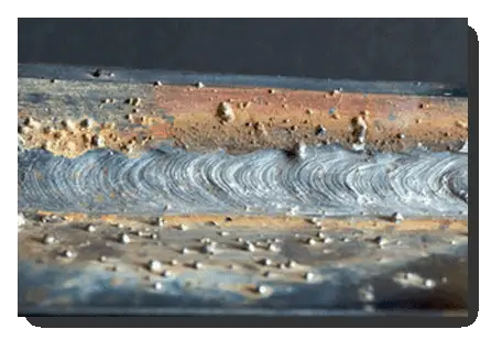
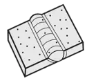
How do you avoid weld spatter?
- Reduce welding current (stick) and arc length.
- Reduce welding voltage (MIG/MAG and flux-cored) and contact tip to work distance.
- Clean the weld surface before welding.
- Check that consumables were correctly baked (covered electrodes and submerged arc flux) and that they have not been exposed to moisture (all consumables).
- Clean the nozzle to clear the shielding gas path (MIG/MAG and flux-cored).
Overlap
Overlap is excess fusion zone metal lying over the base metal at the weld toe without being fused to it. It arises from inadequate process control, inadequate selection of welding materials or inadequate preparation of the materials before welding.
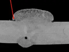
How do you avoid overlap?
- Manipulate the torch correctly so that material is fused and deposited properly onto the base metal.
- Select consumables and welding parameters per the WPS.
- Try to improve the welding position towards flat.
Lack of penetration
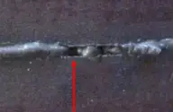
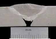
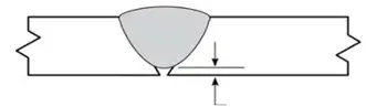
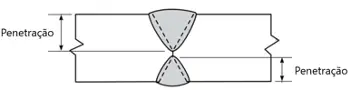
Lack of penetration is a weld that has not fused both sides of the base metal at the joint root.
How do you avoid lack of penetration?
- Prepare the groove with an appropriate root opening and root face.
- Back gouge the root.
- Change the process to double-sided TIG.
- Correct joint misalignment.
- Increase welding current.
- Adjust the electrode angle.
- Manipulate the torch correctly so that material is fused and deposited properly onto the base metal.
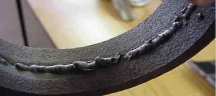
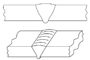
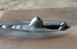
Excessive penetration / burn-through
Excessive penetration, also called burn-through, is an excessive deposit of weld metal at the joint root, causing material to run beyond the root of the joint.
How do you avoid excessive penetration / burn-through?
- Reduce welding voltage and current.
- Increase travel speed.
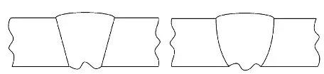
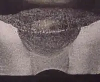
Root concavity
Root concavity is a discontinuity located exclusively at the root, caused by contraction of the weld pool, and as the name suggests it has a concave appearance.
How do you avoid root concavity?
- Reduce travel speed.
- Increase welding current.
Cracks
Cracks are local defects, formed in the weld and/or in the base metal when localised stresses exceed the ultimate strength of the material. Depending on the material they can occur at high temperature during solidification of the weld metal, or some time after welding. High residual stress and hydrogen embrittlement are causes of crack formation. Welding cracks are brittle in nature, showing little plastic deformation at the crack boundaries.
Types of crack
Solidification cracks
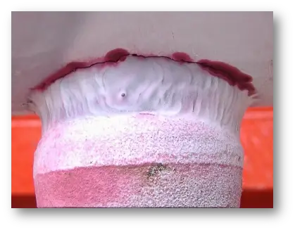
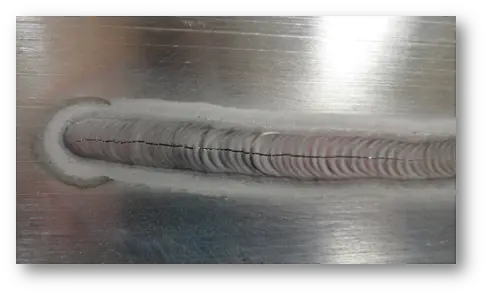
Solidification cracks occur during solidification of the weld pool, driven by high stress concentration and the segregation of impurities during solidification. They are most common in austenitic stainless steels and nickel alloys.
How do you avoid solidification cracks?
- Reduce travel speed.
- Increase the electrical welding parameters.
- Weave the weld pool more.
Hydrogen induced cracking
Cracking induced by hydrogen that diffuses into the weld metal during cooling. Caused by moisture or hydrogen in the consumables or the joint combined with rapid cooling.
How do you avoid hydrogen induced cracking?
- Use low-hydrogen processes and consumables.
- Check that consumables were correctly baked (covered electrodes and submerged arc flux) and that they have not been exposed to moisture (all consumables).
- Preheat the joint before welding and keep the interpass temperature above the preheat temperature.
- After welding, apply a thermal blanket to cool slowly, or carry out post-heating (if the material is high carbon or high strength).
Underfill
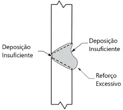
Underfill is a shortage of weld metal on the face of the joint, leaving the material below the level of the base metal.
How do you avoid underfill?
Simply run another weld pass.
Excessive reinforcement
This discontinuity is excess weld metal on the face of the joint.
How do you avoid excessive reinforcement?
- Remove the excess reinforcement by grinding or machining.
- Increase travel speed.
- Reduce the electrical welding parameters.
Arc strike
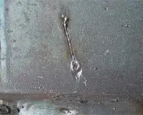
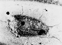
This defect is a local imperfection on the surface of the base metal, characterised by a slight addition or loss of metal caused by striking the arc.
How do you avoid arc strikes?
- Strike the arc in the groove or bevel, on the weld bead, or in the area that will be welded, so it is remelted by the weld pool.
- Use a high-frequency arc ignition system for the TIG process.