July 15, 2024
Welding positions: a complete guide to 1G-6G and 1F-4F (AWS and ASME)
Welding positions are defined by welding codes such as AWS (American Welding Society), ASME (American Society of Mechanical Engineers) and others, as follows:
Groove (butt) joints
Positions on a butt joint are designated by a number representing the degree of difficulty, followed by the letter G for “groove”.
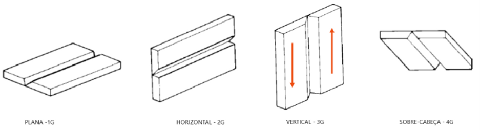
Flat (1G): the torch is at 90° to the horizontal plane.
Horizontal (2G): the torch is parallel to the horizontal plane and progression is horizontal.
Vertical (3G): the torch is parallel to the horizontal plane, but progression is upwards (uphill) or downwards (downhill).
Overhead (4G): the torch is at 270° to the horizontal plane.
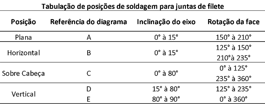
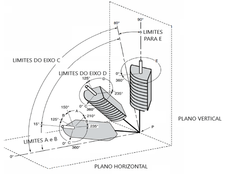
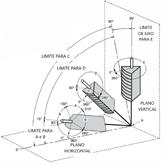
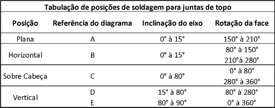
Because positions are not always exactly as in the figure above, the codes standardised a chart and a table defining how the welding position is to be calculated in other situations, according to the inclination of the joint and the rotation of the weld face:
Pipe joints
On pipe joints, because of the curvature of the pipe, the positions are somewhat different:
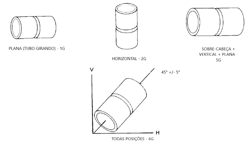
Flat (1G): the torch is at 90° to the horizontal plane (pointing downwards) and the pipe must be rotating.
Horizontal (2G): the torch is parallel to the horizontal plane and progression is horizontal.
Position 5G: the pipe is fixed, positioned horizontally with the joint vertical, and the welder has to start welding from the bottom upwards or from the top downwards, so that during welding the following positions all apply: overhead, vertical and flat.
Position 6G: the pipe is fixed at 45° to the horizontal plane and the welder has to start welding from the bottom upwards or from the top downwards, so that during welding every position applies: overhead, vertical, horizontal and flat.
The figure below makes this clearer:
When welding a pipe positioned differently from 1G and 2G, different combinations of positions can appear depending on how the pipe sits. To determine the positions on the pipe you have to use the groove joint table given above, together with the chart below:
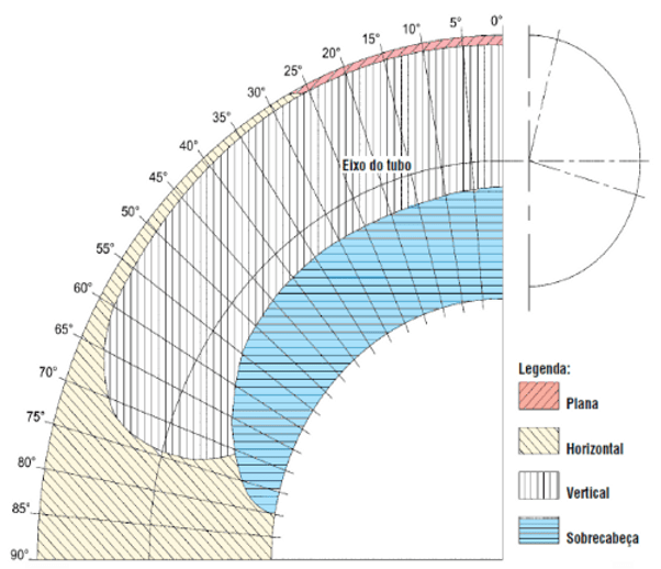
To use this chart, measure the circumference of the pipe and its angle of inclination, find that angle on the chart, project the lines onto the pipe sketch to the right of the chart with a compass or rule, then measure the angle and calculate the arc to mark out on the pipe.
Step-by-step calculation of welding positions on pipe joints
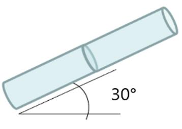
Step 1 - calculate the arc length of each welding position on a 10“ schedule 40 pipe with an outside diameter of 273 mm, inclined at 30°.
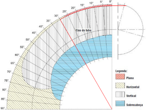
Step 2 - identify and project on the chart:
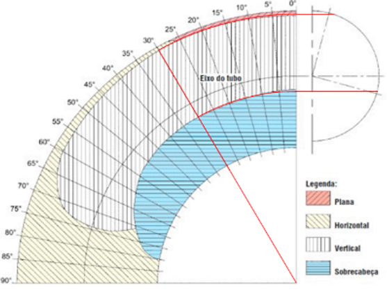
Step 3 - mark out the angles and take the measurements with a protractor:
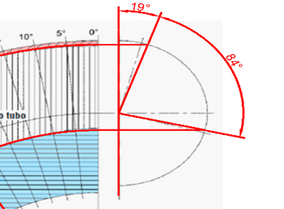
The calculation then follows the steps below.
Calculate the circumference:

Half the circumference = 857/2 = 428.5 mm
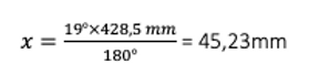
Applying the rule of three:
If 180° = 428.5 mm
Then 19° = x mm
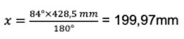
For 84°:
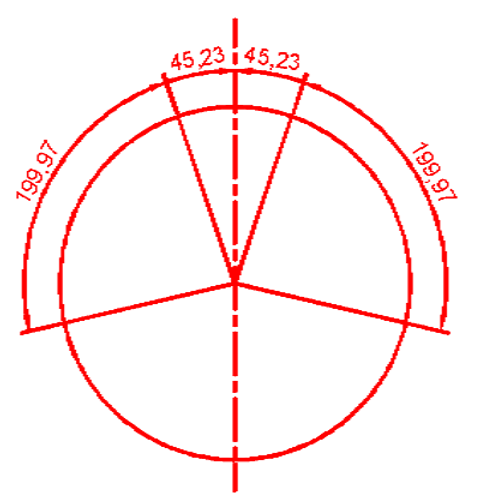
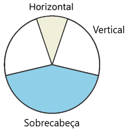
Marking it out on the physical pipe as follows:
Fillet welds
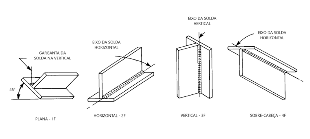
Similar to groove positions, fillet positions are distinguished by the letter “F” for fillet rather than “G”.
The positions are shown in the figure below: