
July 15, 2024
MIG/MAG (GMAW) welding process
Introduction
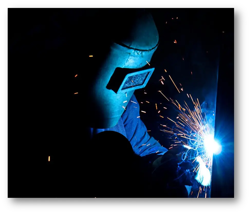
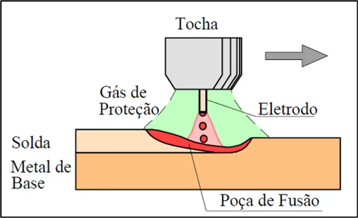
The MIG/MAG process (Metal Inert Gas or Metal Active Gas), designated GMAW (Gas Metal Arc Welding) by the AWS, is the welding process characterised by the use of a solid wire electrode fed continuously through the torch, forming an arc under gas shielding, with metal transferred continuously.
Development of the MIG/MAG process began in 1920, but it took some years before it was applied at industrial scale on aluminium in 1949. Today it is present in most companies that weld.
In MIG/MAG welding the shielding gas has a strong influence on weldability, quality, penetration and weld appearance, so different gases change the character of the process. That is why it has two different names:
- MIG (Metal Inert Gas) - when the shielding gas is inert and does not combine or react with the deposited metal. Argon (Ar) is the gas commonly used, though helium (He) can also be used, at 4 to 5 times the cost of argon.
- MAG (Metal Active Gas) - when the shielding gas is active, combining with the metal and altering the properties of the deposit. CO2, or mixtures of Ar, O2 and CO2, are generally used.
Shielding gases
The table below shows how welding characteristics differ between argon and CO2 shielding gas:
| Variables and characteristics | Argon | CO₂ |
|---|---|---|
| Arc length | Longer | Shorter |
| Ionisation potential | Higher | Lower |
| Arc temperature losses by radiation | Higher | Lower |
| Weld pool temperature | Lower | Higher |
| Penetration | Lower | Higher |
| Arc cross-section | Smaller | Larger |
| Bead width | Narrower | Wider |
| Bead height | Higher | Lower |
| Droplet volume | Smaller | Larger |
| Droplet frequency per second | Higher | Lower |
| Appearance | Better | Worse |
| Arc stability | Higher | Lower |
| Bead hardness | Higher | Lower |
| Molten metal temperature in the pool | Lower | Higher |
As you can see, each gas has different characteristics. So in applications requiring penetration (a CO2 characteristic) combined with good appearance, better stability and less spatter (argon characteristics), a mixture of the two gases in proportions of 18% to 25% CO2 in argon is commonly used.
In some cases mixtures such as argon + CO2 + O2 can be used to increase penetration further.
Modes of metal transfer
In this process, metal transfer - the transfer of the droplet of molten filler metal to the weld pool - can occur in different ways depending on the voltage and current used:
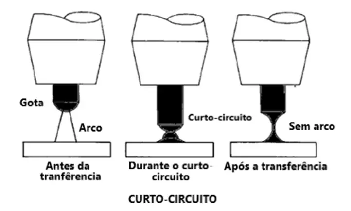
Short circuit transfer - at very low electrical parameters, the filler metal is transferred from the electrode to the weld pool through the surface force between the electrode tip and the surface of the pool. This mode is mostly used for root passes and is not recommended for other applications, since being a low-energy process it can produce lack of fusion between passes, and it is not very productive.
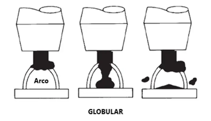
Globular transfer - at moderate electrical parameters, the filler metal detaches from the electrode under gravity in the form of globules. It can be used for fill and cap passes but produces a lot of spatter.
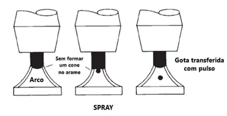
Spray transfer - at high electrical parameters, filler metal transfers as fine droplets following the direction of the magnetic field created by the arc, with gravity effectively irrelevant. This mode is very stable and spatter-free. Ideal for fill and cap passes and high deposition, but applicable only in the flat position.
Pulsed arc transfer - electrical parameters are controlled by a high-technology power source that maintains a low-current arc, keeping the arc alive while a droplet of molten metal forms on the wire tip; at a set frequency, high-current pulses transfer the droplet to the weld pool. The resulting waveform of the pulsed arc process is shown below.
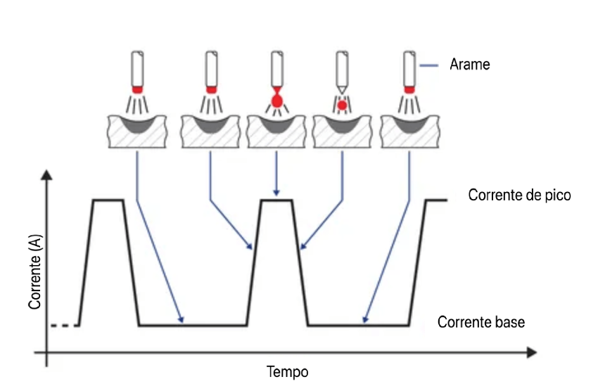
To provide that electronic control, pulsed-arc MIG/MAG requires advanced power sources that cost more than conventional ones - but the welds are produced with high quality, arc stability, high deposition and relatively low welding energy.
Equipment
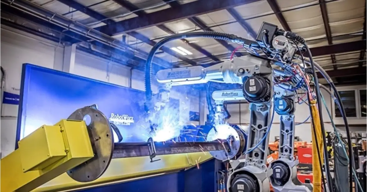
In MIG/MAG the wire is fed semi-automatically: the welder pulls the torch trigger and the wire is fed automatically by the feeder. The process is fully automatic when that trigger action is performed by a robot, for example. The figure below shows the equipment making up the process:
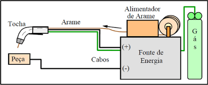
- Power source: the sources used are direct current, constant voltage, and in most cases reverse polarity (electrode positive).
- Gas supply: shielding gas cylinder with pressure and flow regulators.
- Torch: the device the wire electrode passes through, which conducts the welding current and provides the gas shielding the arc needs.
- Wire feeder: the device holding the wire spool, with rolls that drive the wire continuously up to the torch, removing the need for the welder to manage the consumable by hand as in TIG and stick welding.
Because of the characteristics of this process and of pulsed arc control, it is used in around 94% of arc welding robots, and is applicable in almost every type of industry: automotive, heavy engineering, agricultural equipment and machinery, sugar and ethanol, oil and gas, pulp and paper, among others.